Over the past few decades, transesophageal echocardiography (TEE) has evolved from one-dimensional imaging using a probe with a single-crystal, M-mode transducer to two-dimensional imaging with phased-array transducers and now three-dimensional (3D) imaging with matrix array transducers. Current 3D imaging probes are vastly superior to the earlier technique of using multi-plane TEE imaging to reconstruct 3D images. While these earlier techniques enabled improved visualization of valvular anatomy, acquisition of images was tedious and time-consuming and extensive post-processing was required to generate images. As well, image quality was poor and frequently affected by artifact limiting its use for research purposes.
Recent advancements in real-time three-dimensional (RT3D) TEE have propelled 3D TEE imaging into clinical practice from the research realm. With the development of the matrix array TEE probe real-time acquisition and on-line display of 3D TEE images are now easy to acquire and there is no need for either sequential multi-plane acquisition or off-line reconstruction. These images have enabled the visualization of valvular anatomy from unique orientations with improved spatial relationships not previously seen with 2D echocardiography.1,2 In particular, RT3D TEE has allowed improved visualization and assessment of prosthetic valves.3,4 In this editorial, we will discuss the use of RT3D TEE in the assessment of prosthetic valves, their associated complications such as prosthetic valve endocarditis and paravalvular regurgitation as well as limitations and future uses of RT3D TEE.
EvaluationTo acquire 3D images, standard 2D images should first be used to locate the best plane for imaging the prosthetic valve. Then, gain settings should be optimized using narrow-angled acquisition mode, which allows real-time 3D imaging without the need for electrocardiographic gating. Subsequently, 3D zoom mode, with the biplane image feature should be used to focus on the prosthetic valve and acquire images. After that, color, full-volume acquisition should be performed. This mode requires ECG gating because the data set is compiled by merging 4–7 narrower pyramidal scans obtained over 4–7 heartbeats. Once the 3D data sets are acquired, they can be cropped to optimally visualize cardiac structures.
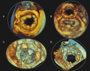
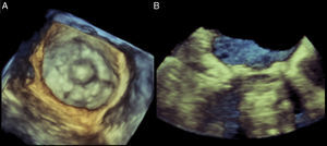
RT3D imaging has been shown to be suitable for the clinical evaluation of prosthetic valves (Figure 1, Figure 2).3 In our study, Sugeng et al., examined 40 patients with normally functioning, prosthetic, mitral, aortic or tricuspid valve replacements or mitral valve repair using RT3D TEE. Of the 40 patients, ten were in atrial fibrillation at the time of the TEE study. Two independent reviewers graded the quality of the prosthetic valve visualization on the images obtained. Images were graded zero if there was inadequate visualization; one if there was more than 75% visualization and/or the presence of motion artifact; and two if there was more than 75% visualization without dropout or motion artifacts.
Figure 1. Real-time three-dimensional transesophageal echocardiography (RT3D TEE) image of a St. Jude's mitral annuloplasty ring (A) as viewed from the left atrium with the aortic valve oriented at the 12 o’clock position. The native mitral valve leaflets are open. RT3D TEE image of a geoform mitral annuloplasty ring (B) as viewed from the left atrium with the native valve leaflets closed. RT3D TEE images of a normal bioprosthetic mitral valve as viewed from the left ventricle with the leaflets closed (C) and open (D).
Figure 2. Real-time three-dimensional transesophageal echocardiography image of a Starr-Edwards valve in the mitral position as viewed from the left atrium during ventricular systole (A) and sagittal cropped plane (B) depicting the cage of the mechanical valve.
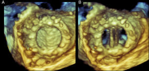
This study demonstrated that in normal mitral mechanical and bioprosthetic valves, the rings, leaflets and struts can be clearly visualized from both the left atrial (Figure 3) and left ventricular perspectives in the majority of patients. In contrast, although 2D TEE had improved the visualization of the left atrial side of a mechanical mitral valve over transthoracic echocardiography (TTE), shadowing from the posthesis consistently prevents examination of the prosthesis from the left ventricular side.
Figure 3. Real-time three-dimensional transesophageal echocardiography of a normal mechanical mitral valve visualized from the left atrium with the leaflets in systole (A) and in diastole (B).
We also reported that in patients with mitral valve repair the mitral annuloplasty ring and anterior leaflet were optimally visualized in 100% and 60% of cases, respectively.3 This was irrespective of whether the prosthetic valve was visualized from the left atrial or left ventricular perspective. However, the posterior leaflet was only optimally visualized in 40% of patients irrespective of perspective.3
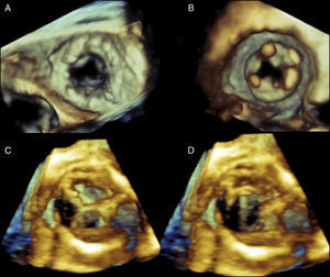
With regards to aortic mechanical and bioprosthetic valves, the leaflets are poorly visualized regardless of perspective. Importantly, the aortic valve prosthetic ring was well visualized from both the left ventricular outflow and aortic perspective (Figure 4). Similar to the visualization issues with prosthetic aortic valves, in tricuspid prosthetic valves, the prosthetic ring could also easily be visualized whereas the tricuspid leaflets were poorly visualized. The common difficulties in adequately visualizing both the aortic and tricuspid prosthetic valve leaflets are likely due to the fact that these valves lie farther from the transducer and that their location is oblique to the angle of incidence of the ultrasound beam. This is likely the same reason why visualization of native aortic and tricuspid valve leaflets is relatively poor compared to the mitral valve. Ideally, technological improvements are still required before RT3D TEE imaging is optimal for the assessment of prosthetic valves in these two anatomic locations.
Figure 4. Real-time three-dimensional transesophageal echocardiography (RT3D TEE) of a normal bioprosthetic tricuspid valve during diastole oriented as seen from the right atrium (A) and the right ventricle (B). The tricuspid ring is easily visualized but the leaflets are poorly seen. RT3D TEE of a normal bioprosthetic aortic valve oriented as seen from the aorta (C) and the left ventricular outflow tract (D). Again, the aortic leaflets, in contrast to the ring, are poorly visualized. See text for explanation.
Overall, RT3D TEE imaging allows clinically useful visualization of prosthetic valve components such as the leaflets, rings and struts of all prosthetic valves irrespective of position. This is especially useful for the assessment of mechanical mitral and aortic valves where 2D images are often of poor quality due to acoustic shadowing. In particular the RT3D allows visualization of ventricular side of mitral prosthetic valves. One last important point in using RT3D TEE for the assessment of prosthetic valves is that it does not substantially lengthen procedural time. Acquisition times for RT3D TEE imaging routinely require approximately 10 additional minutes.
Prosthetic valve endocarditisEchocardiographic findings are one of the factors that are included in the Duke Criteria for diagnosing infective endocarditis. While TTE has relatively high specificity for detecting vegetations, its sensitivity lies between 40 and 80%.5 Thus, TEE is often performed when the clinical suspicion of infective endocarditis is high and TTE is negative or inconclusive. In general, prosthetic valve evaluation using TTE is difficult or insufficient due to the frequent presence of shadowing originating from adjacent prosthetic valve tissue. Accordingly, when the clinical question of infective endocarditis arises, these patients often require an additional TEE study to assess valvular structure and function.
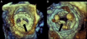
RT3D TEE has been shown to provide additional information in the evaluation of prosthetic valve endocarditis (Figure 5).4 Due to the acquisition of wide-angled, full-volume data sets and the ability to manipulate and crop images, deep anatomical structures can be clearly displayed compared to conventional TTE or TEE. As well, 3D TEE images are not limited to 2D planar views enabling valvular visualization at angles not previously possible. Particularly, the “en-face” view of prosthetic valves has been useful in the assessment of prosthetic valve endocarditis as it allows the identification of discrete valvular dehiscence together with associated regurgitation jets. The ability to display valvular images in a surgical perspective allows for better communication with surgeons.
Figure 5. Real-time three-dimensional transesophageal echocardiography of a bioprosthetic mitral valve with vegetation on the atrial side of the leaflet as visualized from the left atrium (A) and left ventricle (B). In image B, the struts of the bioprosthetic valve are clearly visible. Black arrow points to the vegetation.
In prosthetic valve endocarditis, RT3D imaging has been shown to correlate well with surgical and 2D TEE findings and has been shown to identify additional vegetations not seen on 2D TEE.4 RT3D images can also assist in the differentiation of vegetation versus loose suture material and the rocking motion of a partially dehisced valve is better appreciated on RT3D imaging.
Paravalvular regurgitationThe incidence of significant prosthetic paravalvular regurgitation causing heart failure and hemolytic anemia is 1%–5% and the majority of prosthetic leaks generally occur in the first year post-valve replacement.6 Overall, it has been estimated that up to 10% of prosthetic aortic valves and up to 15% of mitral valves have some degree of paravalvular regurgitation. Significant paravalvular regurgitation requires intervention, which may be surgical or percutaneous. Traditionally, surgical treatment of paravalvular regurgitation was standard practice. However, over the past 20 years, transcatheter closure methods of paravalvular regurgitation have been developed, though its use has been limited due to the lack of imaging techniques to accurately locate the paravalvular leak. RT3D TEE plays an important role in: (1) the evaluation of paravalvular regurgitation (size and location); (2) guidance during interventions to treat significant paravalvular regurgitation; and (3) post-interventional assessment.
Assessment of Paravalvular RegurgitationAssessment of paravalvular regurgitation in prosthetic valves is performed primarily using echocardiography. TEE consistently provides superior images compared to TTE in the assessment of prosthetic valves due to the proximity of the esophagus to cardiac structures. However, 2D TEE can miss significant findings as it only presents images from a thin imaging plane through the heart.
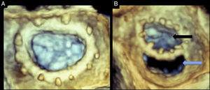
Three-dimensional TEE provides 3D images that can display the entire prosthetic valve, especially those in the aortic or mitral positions.3 Specifically, the 3D zoom modality can provide en-face views of both the mitral and aortic valves. By convention, the mitral valve image, as viewed from the left atrial perspective, is rotated to position the aortic valve at 12 and the left atrial appendage at 9 o’clock. Dehiscence sites can be identified, with special attention to their location, shape, size and area. Using multiplanar imaging it is possible to quantify the area of the dehiscence (Figure 6). Full volume acquisition provides wider angle images with higher temporal resolution. After data acquisitions, data sets can be rotated, manipulated and cropped to obtain optimal exposure of paravalvular leaks. The presence of paravalvular orifices can be confirmed with the use of three dimensional color flow.
Figure 6. Real-time three-dimensional transesophageal echocardiography of a normal mitral annuloplasty ring (A) and a mitral annuloplasty ring dehiscence (B). Both images are oriented as viewed from the left atrium. Black arrow points to the annuloplasty orifice. Blue arrow points to the posterior annuloplasty dehiscence. The dehiscence is located in the posterior aspect of the ring. See text for explanation.
In mitral valve dehiscence, RT3D TEE provides incremental information regarding the exact anatomic characteristics of the dehisced area as well as information on the relationship between the dehiscence, mitral regurgitation jet and adjacent anatomical structures (Figure 7). It has been recently described that mitral valve dehiscences occur mainly in the posterior or lateral region and are very rarely located anteriorly.7 Four theories have been postulated to explain why ring dehiscences are more likely to occur in the posterior region of the mitral annulus. These theories generally relate to limitations of the surgical field and structures surrounding the mitral valve apparatus. The first theory is that the posterior mitral valve annulus is in the far surgical field providing a limited window for the surgeon while suturing. The second theory is that the surgeon is attempting to avoid harming the circumflex artery, which often results in more superficial suturing posteriorly. The third theory is that calcifications and fibrosis of the mitral annulus are more prevalent posteriorly making it more difficult to ensure proper suturing. Lastly, it has been suggested that the anterior portion of the mitral annulus is comprised of the mitral fibrosa. This provides a relatively solid interphase into which the surgeon can sew the valve comfortably. However, it also lacks flexibility and can therefore tether the annulus causing tension, which in turn pulls at the posterior portion of the annulus placing that site at a higher risk of dehiscence.
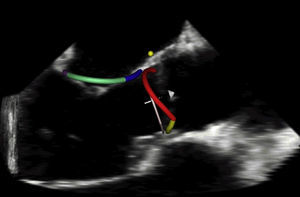
Figure 7. Real-time three-dimensional transesophageal echocardiography with simultaneous automated tracking of the mitral and aortic annuli used for studying the coupling between the valves.
Intervention in Paravalvular RegurgitationOverall, RT3D TEE has been shown to provide a more accurate assessment of the exact site and size of the leakage in patients with known prosthetic paravalvular regurgitation.8,9 This is important in deciding whether the patient will undergo a surgical or transcatheter approach for the correction of the paravalvular regurgitation. For the surgical approach, providing information on the size and location of the leak prior to cardiopulmonary bypass will assist the surgeon, as it may be difficult to obtain this information once the heart has been deflated of blood. As well, RT3D TEE can evaluate the presence of residual regurgitation after the patient has been weaned off cardiopulmonary bypass and before the chest is closed which would prevent the need for reoperation.
When a percutaneous approach is taken to close a paravalvular leak, 3D TEE plays an important role in determining the route of approach as well as the choice of closure device.7 Depending on the valve, the approach can be antegrade or retrograde. For example a paraprosthetic mitral valve leak can be accessed from the left atrium after a transseptal puncture (antegrade approach) or from the left ventricle after a left ventricular apical puncture (retrograde approach).10 Currently, small paravalvular leaks are occluded using an Amplatzer patent ductus arteriosus (PDA) device while larger paravalvular leaks require larger Amplatzer ventricular septal defect devices. This decision can be made after measuring the area of dehiscence in multiplanar views.
During percutaneous device closures of prosthetic paravalular leaks, RT3D TEE images of the cardiac structures, catheters and occlusion devices are used to guide the operator during the various stages of the procedure. Such stages include selection of the site for the atrial transseptal puncture, and guidance of the catheter and the device into the paravalvular leak. The major advantage of RT3D imaging in this procedure is the ability to visualize the entire length of intracardiac catheters, as well as the balloons or devices attached to the catheters and their position in relation to important cardiac structures.11,12 To acquire this visualization field a single probe and transducer angle is needed. The constant manipulation and rotation required with 2D imaging techniques is eliminated.
RT3D imaging also allows the continuous assessment of the prosthesis’ function before, during and after the procedure. In addition, post-procedure, RT3D TEE imaging can assess the location and function of the occluder device and any possible complications such as the creation of a new paravalvular leakage site caused by stretching of the suture line during device deployment.
LimitationsLimitations of 3D TEE includes poor visualization of anterior structures of the heart, suboptimal images due to poor ECG triggering in patients with arrhythmias, reduced spatial and temporal resolution with narrow angled acquisitions as well tissue dropout. Anterior cardiac structures such as the aortic and tricuspid valves due to their increased distance from the TEE probe cannot be visualized as well as posterior structures such as the mitral valve.
Patients with valvular heart disease often present with arrhythmias at the time of their echocardiographic study. Historically, these arrhythmias led to suboptimal images with artifacts due to poor ECG gating during image acquisition. This issue has now been resolved with the recent development of single-beat, real-time, full-volume data acquisition in transesophageal probes. It has been available clinically in transthoracic probes and in this setting its use has resulted in reduced imaging artifacts and improved the evaluation of patients with arrhythmias. Additionally, the combination of RT3D imaging in the 2D TTE probe has facilitated the clinical use of 3D echocardiography, as echocardiographers no longer have to switch probes mid-study to acquire 3D images.
Traditionally, 3D zoom mode provides images of high spatial resolution at the expense of temporal resolution with frame rates typically less than 10Hz. This may hamper the ability to visualize fast moving structures such as vegetations and dynamic behavior of mitral rings. This limitation has been recently overcome with the introduction of new software that allows imaging at higher rates approaching 30Hz. New 3D echocardiographic systems allow full-volume acquisition using one to two cardiac cycles due to higher volume rates. This results in images that require only a short acquisition time while minimizing stitch artifact and improving resolution. In TTE, this type of acquisition has been shown to provide similar accuracy to RT3D imaging data acquired using conventional four beat acquistion.13
Alternatively, another approach to increasing temporal resolution with frame rates greater than 30Hz is to use wide-angle, full-volume acquisition. However, the risk of stitch artifact may be increased due to the requirement for multiple cardiac samplings over four to seven beats. This usually results in artifacts in more than 70% of cases. However, these generally do not compromise the diagnostic yield of the test. Users must be particularly aware of this limitation in the acquisition of color Doppler data sets as the acquisition spans seven cardiac cycles. In the operating room, stitch artifact can be eliminated by briefly interrupting the respirator during image acquisition.
Tissue dropout may occasionally be interpreted as an anatomic defect while increasing the gain may results in blurry images. However, experience as well as combining information of several imaging planes and using color and Doppler information will help differentiate between a true defect and tissue dropout.
Future directionsRecently, RT3D imaging has been used to demonstrate in normal humans that the aortic and mitral valves, which are linked via fibrous tissue, share inversely, reciprocal annular changes throughout the cardiac cycle (Figure 7).14 This has lead to preliminary work examining the effect of prosthetic aortic valves on mitral annular dynamics through aortic–mitral coupling. The ability to study these changes through RT3D imaging may have an eventual impact on valvular surgical interventions and prosthesis design.
ConclusionsRT3D imaging is an excellent imaging tool that adds to the available information provided by traditional imaging modalities. In the assessment of prosthetic valves, especially mechanical valves, RT3D imaging allows improved visualization over 2D techniques. One example of this is visualization of the mitral prosthetic valves from the ventricular perspective. Another major advantage of RT3D imaging is the ability to display unique views not available from traditional 2D imaging. Specifically, the “en-face view of valves” has proven useful in the assessment of prosthetic valve endocarditis and paravalvular regurgitation. As well for paravalvular regurgitation, RT3D imaging plays an important role in determining the method of closure, and in the case of catheter-based device closure, guidance in the closure procedure. There are a few limitations to RT3D imaging such as poor visualization of anterior cardiac structures, poor temporal resolution, poor image quality in patients with arrhythmias and tissue dropout. However, these can be addressed with newer technology and training. Overall, RT3D imaging is a technology that improves the visualization in the assessment of prosthetic valves.
Conflict of interestDr. Itzhak Kronzon reports receiving honoraria from Philips and research grant from General Electric.
Corresponding author 5841 South Maryland Avenue, Chicago, Illinois 60637, United States. rlang@medicine.bsd.uchicago.edu
